By corners and edges I mean where the inside of a flange meets the top and bottom of the web and on the outside edges of the flanges themselves. Two 8 mm fillets for 10 mm thick plates For beams over 610 mm nominal depth the span to depth ratio of beam should not exceed 20 and the vertical distance.

Pin On Steel
Direction Method as BS 5950 clause 6873.
Welding i-beams perpendicular. The principal stresses are therefore in a longitudinal direction and any stress raisers 90 to this direction are bad news. Two fillet welds in parallel shear Because of zero values of and the plasticity criteria is simplified to The side welds. A relatively small depth of material will become molten and upon cooling the structural steel and weld metal will act as one continuous part where they are joined.
The job Im on right now is a remodel and one of the trades is hanging their pipe off existing I-beams. Youll want to unload the beam as much as you can during this as the weld heat will take a bit of your beam capacity during the welding. 1 Perform as little welding on the bottom flange as possible.
L Length of weld 1 unit thick From table below b d 120 150 270mm To obtain radius of Force from weld Centre of Gravity Cog. Welding I Beams Perpendicular September 26 2018 - by Arfan - Leave a Comment Advance design steel connections solved problem 1 an i beam is to be laser welded corrugated core welded joints of rolled and weld structural ering general. Weld length for any groove weld square or skewed shall be the width of the part joined perpendicular to the direction of tensile or compressive stress.
As in the advantages above I-Beams do well for longer beams with a higher load. The effective area shall be the ef-fective weld length multiplied by the weld size. H-beams also have a combined section consisting of 3 plates welded together.
Structural welding is a process by which the parts that are to be connected are heated and fused with supplementary molten metal at the joint. The weld throat thickness should be 253 220 115mm. The angle formed between a centerline perpendicular to the wall and the cut face of the wall.
This beam profile is very versatile especially when we add in all the fabricated and bent beam shapes. For groove welds transmit-ting shear the effective length is the length specified. Fillet weld in perpendicular shear.
The flat and perpendicular sides make drilling easy too at least in one direction. We failed to cut the taper in. 115 162mm use 3mm fillet weld.
Theyre welding Uni-strut to the bottom flange of the beam perpendicular to it then hanging off that with all thread and clamps. Stress created for the three plate splice configuration weld equals plate thickness. Stress created for a Partial Penetration Weld Load Perpendicularity Weld Stress.
Largest β plasma 45 - or. Calculations for optimal weld preparation are based on ψ. The maximum size of a fillet weld is as follows.
The rolling of H-beam steel is different from that of ordinary I. Two Plate Weld Axial Load Weld. Along the edge of a connected part less than ¼inch thick the maximum fillet weld size w equals the plate thickness For other values of plate thickness t the maximum weld size is t 116 in.
A perpendicular cut has β0. Equal to cutting angle and can be negative or positive. For this reason and possibly fatigue reasons dont weld across the flange perpendicular to the long axis of the beam.
3 The weld quality has always been a concern for me in this situation. I cant remember any specifics about this from my structural classes. The weld size is therefore 1414.
I-beams are rolled section. Stress created for the three plate splice configuration weld equals plate thickness. Angle between the outer faces of the connected walls.
Id prefer to weld the two members together with stitch plates if those plates wouldnt interfere with other elements. A 250-27 223mm. This is so because the loading on these beams is mostly bending.
Or when welding in added sections to lengthen a frame. Shear stress perpendicular to the axis of weld shear stress parallel to the axis of weld axial stress parallel to the axis of weld omitted Example 1. I dont see how one would get a reliable weld connecting the channel flanges unless they were prepped for partial penetration welding which would be costly.
The inner edges of the inside flanges have a 110 slope because of the poor production technique. 2 If at all possible the welds need to run in a longitudinal direction. Extend the angle beyond the affected areas to develop the reinforcement.
Fillet weld Fillet weld 1. Further whether I-beam connections end-to-end parallel and end to surface perpendicular should be welded not only on the flange orand web but in the corners and around the edges. SUBSCRIBE for NEW VIDEOS EVERY MONDAY AND FRIDAY httpsgooglFRdNssA few weeks back we showed you how to cope an I-beam.
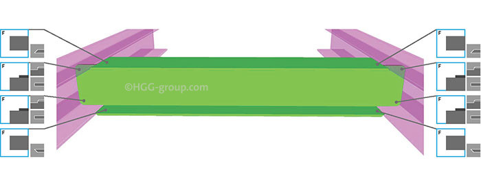
How To Make Strong Welded H Beam Connections Hgg 3d Profiling

Image Result For Connection Between Purlin And Rc Beam Detail Steel Trusses Steel Roofing Metal Roof
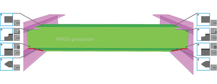
How To Make Strong Welded H Beam Connections Hgg 3d Profiling
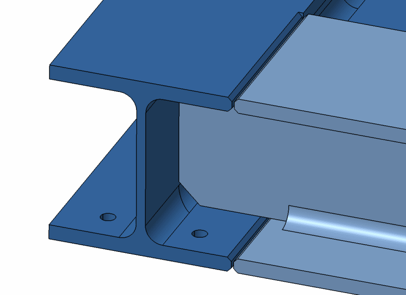
Machining Welding Beads From I Beam Unions Welding Bonding Fastener Engineering Eng Tips

Machining Welding Beads From I Beam Unions Welding Bonding Fastener Engineering Eng Tips

Crane Runway Beam Design Excel Beams Design Concrete Design

Machining Welding Beads From I Beam Unions Welding Bonding Fastener Engineering Eng Tips

Edge Alignment Pins 4 Pack Edges Speed Square Square Tool
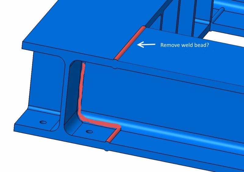
Machining Welding Beads From I Beam Unions Welding Bonding Fastener Engineering Eng Tips


0 comments:
Post a Comment