Final tutorial of the Creo Welding series Thanks so much to everyone here whos supported me. This renders the weld package useless.
Ptc Creo 5 Drawings Welding Symbols Youtube

If using Creo2 select the drawing view in which you want the symbols to appear select the ANNOTATE tab choose SHOW MODEL ANNOTATIONS then pick the SHOW MODEL SYMBOLS tab second tab from the right shown below.
Welding drawing creo. See more ideas about technical drawing isometric drawing mechanical engineering design. In this demonstration we will explore the Welding application in Creo Parametric including weld rod material and parameters weld processes and weld features. 1200 1700 2500 USD Overview.
ProWeld will generate the correct drawing text for the weld but the actual display of the weld sucks. PTC makes it easy to add weld symbols by providing a suite of pre-generated symbols and an options dialog box t. PTC Creo Parametric PTC Creo Elements Rhino SpaceClaim SOLIDWORKS solidThinking Evolve SurfCAM Solid Edge SolidFace STEP IGES SketchUp.
PTC Creo Parametric drawing report welding create how. This engineering drawing present weld type symbols and fillet weld symbols. If you create a new welding symbol you replace an existing symbol in the welding symbols library with the new symbol.
As a general rule it is advisable to redefine an existing weld symbol. A click on a welding seam figure in the 2D drawing reads out the associated information of the 3D model and automatically generates the associated welding seam symbol. When you place welding symbols in your drawing only welding symbol names that are stored in the standard Creo welding symbols libraries are recognized.
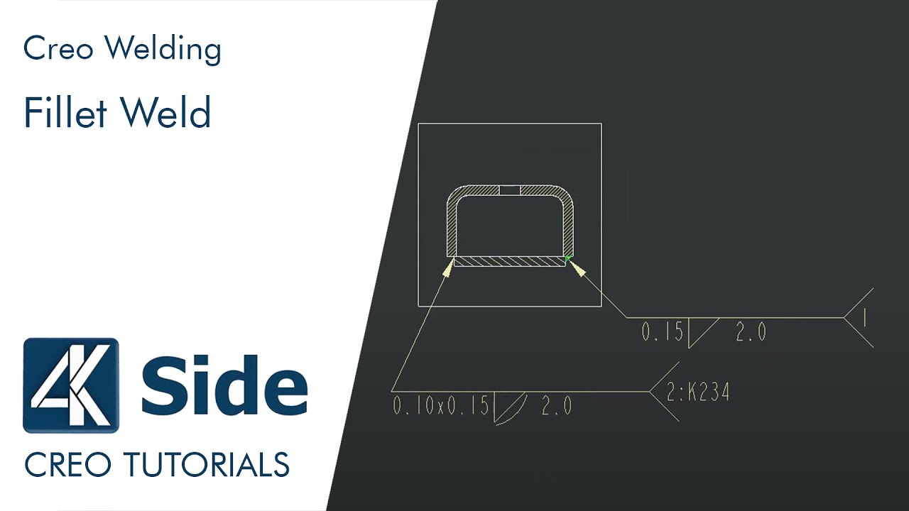
Then once you got the welding done on the assembly the weld symbols that transfered to the drawing were so mis-sized you would end up having to use the manual symbols anyway. Fillet welding refers to the process of joining two pieces of metal together whether they be perpendicular or at. You only have to enter a point to place the icon - done.
Participants in this Creo Weld classes will learn to use the weld utility and generate respective detail drawings with modern drawing standards. This way you wont have displayed welds in drawings. 163240 Hours accordion autoclosefalse openfirsttrue clicktoclosetrue accordion-item titleOverview stateopen Participants in this Creo Weld classes will learn the weld utility and generate respective detail drawings with modern drawing standardsParticipants have the option to customize this course to fit their.
The arrows of the symbol between the two letters indicate that a weld needs to run the full length between the two marks. N95 Mask edge welding. 3D CAD welding seams in PTC Creo ElementsDirect Modeling.
The weld type symbol is typically placed above or below the center of the reference line depending on which side of the joint its on. The symbol is interpreted as a simplified cross-section of the weld. Oct 6 2005 1 Jacoolo New member.
When identification of the weld process is required as part of the weld symbol the relevant weld process code is listed in BS EN ISO 4063. How to place welding symbols on a drawing with PTC Creo 5Music. Participants have the option to customize this course to fit their unique job requirements.
Views 21428 Views Difficulty level Introductory Matt Stirland PTC. Previously it would only handle the simplest of welds. This tutorial is part of a course.
Description How to insert weld symbol in drawing mode. Hello I made an assembly and than make welding with Welding module. Weld between points.
I have tried to work arround this by modeling datum curves then change hatching to get the desired result then turning them off and on by layer by view. An arrow line 2. Introduction to Welding in Creo Parametric.
View the full course. Modeled welds can be added to a part and assembly file in Creo Parametric but for communication purposes adding weld symbols and requirements on an engineering drawing is more important. Im at 100 of my Goals - Creo Welding tutorial series.
Top-Down Design Detailed Drawings. A reference line 3. Oct 11 2019 - Explore shravan swadis board Creo Practice on Pinterest.
How to create Welding report - How to create Welding drawing. Creo Drawing Welds in drawing. Anything that had the list bit of complication was mostly impossible to get documented using Proweld.
How to show welding symbols in drawings Vijay which version of ProE or Creo are you using. Oct 7 2005 3 Jacoolo New member. The problem is that some welds I want to be shown some.
Drawing Page Drawing of Weld Symbols Standards The British Standard for weld symbols is BS EN 22553. You can replace the Creo Parametric-supplied library of system weld symbols with user-defined onesAfter you define the symbols the system uses them for automatic weld annotation. How to insert weld drawing symbol in Creo Parametric Modified.
Is there a library for ISO and ANSI weld symbols. Start date Oct 6 2005. 24-Dec-2020 Applies To ProENGINEER and Creo ElementsPro Wildfire to Wildfire 50.
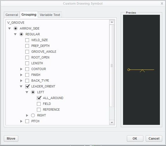
By customizing your weld symbols in advance you can increase your flexibility and productivity throughout the processes of creating and modifying drawings. The drawing will show two points like an X and a Y for example between sections needing welding. Basic Weld Symbol The weld symbol always includes 1.
Creo Parametric 10 to 70. Parasolid May 10th 2021 DIMIDE 14 Series Clamp D.
Solidweld 3d Cad Welding Seams In Ptc Creo Elements Direct Modeling Klietsch Gmbh

Creo Weld Level 15 Design Engine

Creo Weld Level 15 Design Engine

User Defined Parametric Weld Symbols
Creo How To Create Welding Symbols Youtube

Creo Weld Level 15 Design Engine

Creo Welding Tutorial Fillet Weld Surface Weld Type Light Weld Solid Weld Youtube
Tutorial How To Access Welding Symbols In Drawings Creo Parametric 4 0 Omnia Mfg
Creo Weld Level 15 Design Engine


0 comments:
Post a Comment