Welding Across Beam Flange - New Images Beam. Those welds should be parallel to the length of the I-beam.
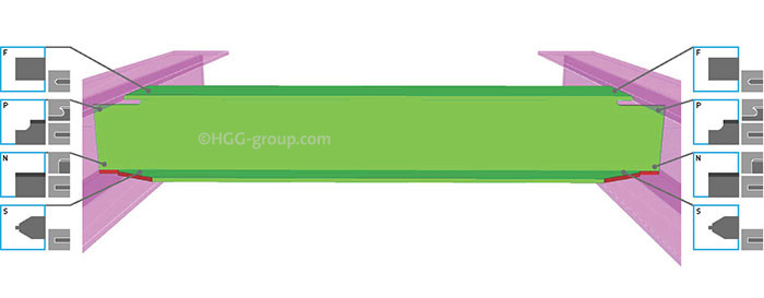
How To Make Strong Welded H Beam Connections Hgg 3d Profiling
A welded beam to beam connection fully fixed for high performance steel structures.
Welding across beam flange. End-Plates are cut from Plate or Flats which are drilled or punched to the required bolt-patterns and shop-welded to the beam-end web. The theory is that if you weld across the flange you introduce excessive heat that can possibly affect the entire flange and possibly cause collapse. There is no reason for such welds since the flange will not take the force.
Depends on where along the beam length you are welding. Note the stiffeners are not welded to the top flange. The weld root and at the outer fiber of the beam flange.
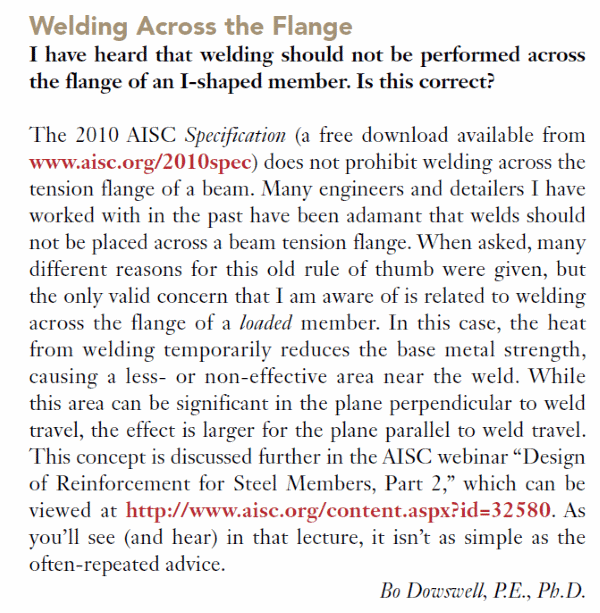
In most cases the weld metal strength will govern. This limited access combined with the desire to eliminate overhead welding usually leads to built-up shapes that are singly symmetric. If shear studs will be installed in the top flanges after painting it is often questioned whether the paint must be removed prior to welding.
Except where the ends of stiffeners are welded to the flange fillet welds joining. Not be placed across a beam tension flange. The Iron workers I have worked with say the same applys to Stuctural beams the difference being in the material and the heat treatment.
Top flange top web bottom web and bottom flange. Examples of flexible con-nections include framing angles top angles of seated beam connections and simple end plate connections. Do not weld the ends.
As to imminent failure. Never weld across the flange but along the Lip. As has been said weld beads across the flange may be acceptable in certain applications better have that RFI in hand first but is not generally recommended for the reasons stated.
Weld that to the flange. Always check weld metal and base metal strength. 621 Limitations on weld dimensions See AISC Spec.
If you weld straight across you weaken it and create undue stresses in the wrong direction plus a HAZ. Your welds should be along the outside edge of the flange on both sides. Merely welding the lug across the more flexible flange would result in an uneven distri bution of load to the weld and to the lug.
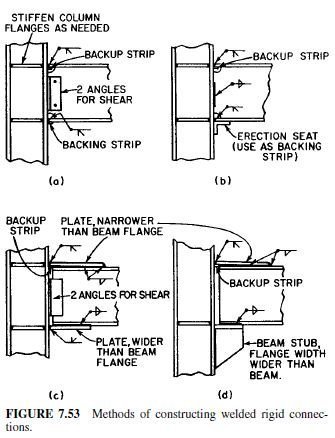
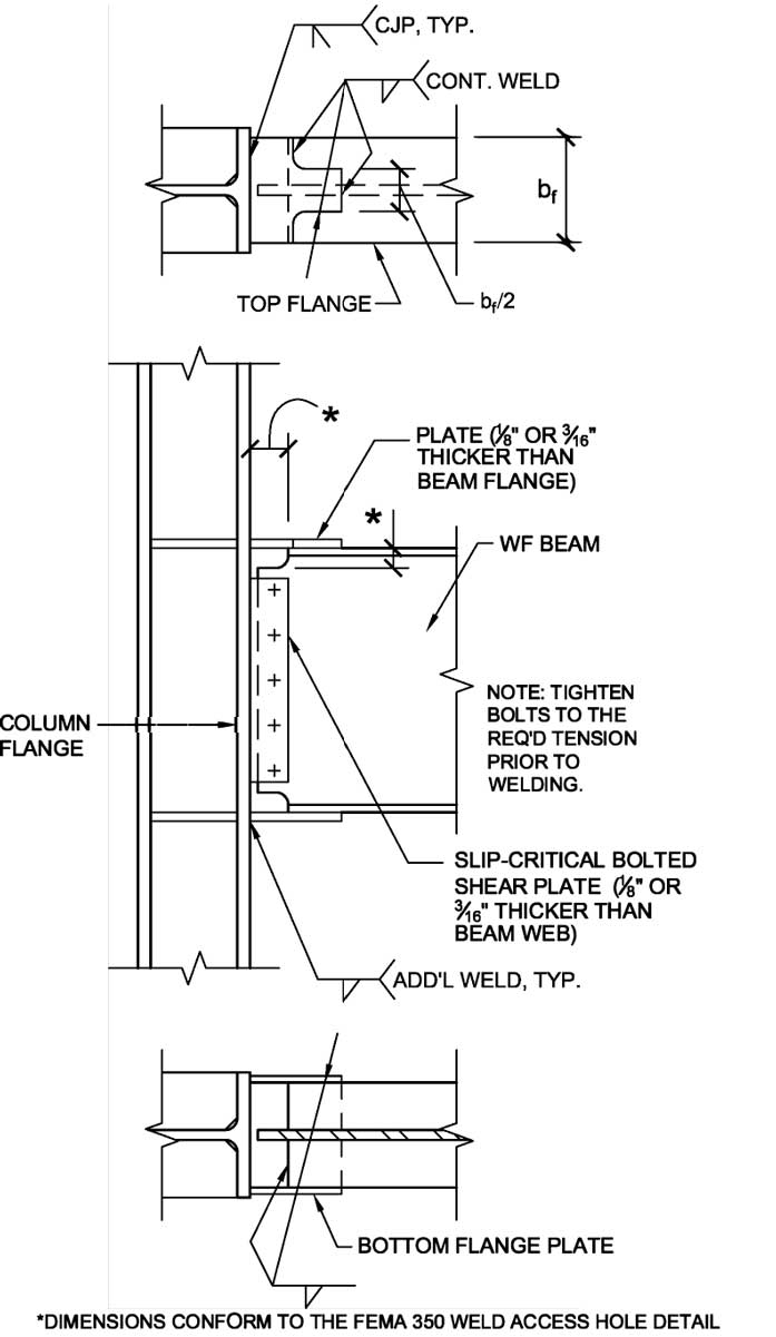
In weld design problems it is advantageous to work with strength per unit length of the weld or base metal. The beam flanges are groove welded to the column flanges and the seat plates and stiffener plates are fillet welded to the column flanges. Welds the length of the end return shall not exceed four times the nominal weld size.
Once the pad is welded in place whatever you want can be welded across the pad with out concern of creating a stress riser in the structural member. Further differential cooling of a weld pass across the width of the beam flange will generate large residual stresses even in the absence of external restraint to the beam since the portions of the weld that cool first will restrain the portions of the weld that cool later for the same weld pass. 8-mm leg on the column flange helps to reduce the stress concentration at the right-angle intersection of the beam flange and column flange and is placed at the location of maximum stress.
While this area can be significant in the plane. W weld length across beam flange usually b fb in Figures 14 and 17 φv w design capacity of fillet weld per unit length weld category SP Fillet welds for economy should be sized to be single pass welds if possiblethis generally means 6 mm or 8 mm fillet welds although some welding procedures will allow 10 mm single. A re-inforcing fillet weld with a 5 16-in.
Four cuts are needed to define a beam end shape. With a steel beam weve always been very careful about trying to avoid welding across a beam flange while it is under stress and carrying load. The possibility always exists particularly on small stuff say something like a loaded W6.
Floor systems roofing or other ob-structions may limit access and prevent welding to both flanges of a beam. If you must weld crosswise first weld a reinforcement to the beam welding lengthwise. The End-Plate is welded longitudinally to the beam web on both sides which should not be continued across the top and bottom of the plate.
The plates are fed to the H Beam Tack welding station for doing single point entry level tacking between the 2 Flanges the Web to form an H configuration. When asked many different reasons for this old rule of thumb were given but the only valid concern that I am aware of is related to welding across the flange of a loaded member. To simulate field conditions for this connection the seat plates and stiffener plates are.
If you can Box it in to distribute the load. Forcing beams and columns as well as welding and tolerance considerations. Then weld crosswise to the reinforcement.
In this case the heat from welding temporarily reduces the base metal strength causing a less- or non-effective area near the weld. Beams Lets start with beams. The web works hardest near the supports and the flanges - especially bottom flanges near midspan should NOT be welded to as they are in the highest level of tension along the beam.
When welding on a beam the first rule is Never weld crosswise. Our H Beam Tack Welder is employed with necessary hydraulic fit-up cylinders which can help the operator. Stress tensor a posite beam electron beam welding eb hining welding be from i beam electrical resistance of laser welded electron beam welding techniques and Field Retrofit Of Steel Beam.
Concerns are that the paint can gas up during welding and might extinguish the weld arc. Stud manufacturers typically recommend that all paint be removed before shooting studs. J22b on page 161-54 of manual Minimum size amin.
25 Variation of Stress Across Beam Flanges Adjacent to Column--C12. The weld preparation is shown on the right side of the cut.
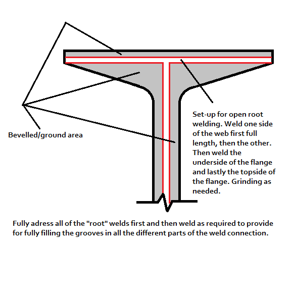
45 Degree Full Pen Prep Of S Beam
Welded Seat Connections Civil Engineering
Structure Magazine Unanticipated Stresses And The Welded Flange Plate Moment Connection
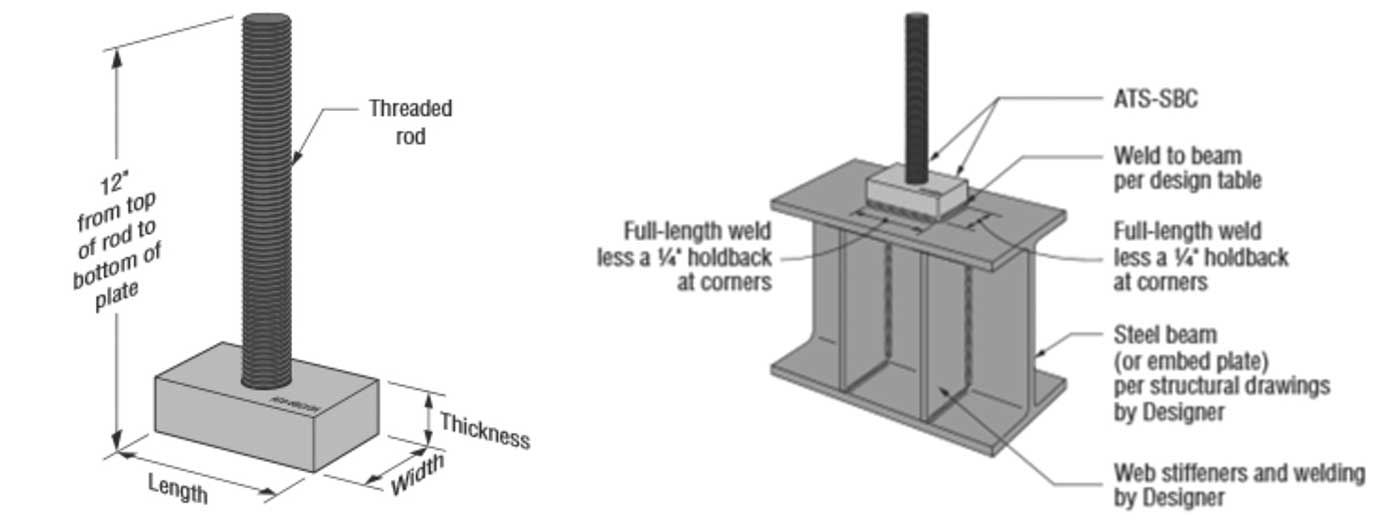
Rod To Steel Beam Connections For Anchor Tiedown Systems Rod Welding Brittle Failure And Alternative Connections Simpson Strong Tie Structural Engineering Blog
Structure Magazine Unanticipated Stresses And The Welded Flange Plate Moment Connection

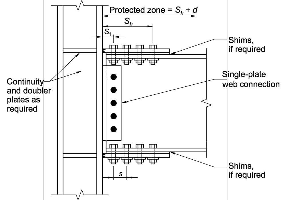
Typical Pre Northridge Welded Flange Bolted Web Moment Connection Download Scientific Diagram
Weld Across The Flange Structural Engineering General Discussion Eng Tips

Typical Pre Northridge Welded Flange Bolted Web Moment Connection Download Scientific Diagram

Weld Wrapping


0 comments:
Post a Comment