For example the projection weld - ing process was simulated with a cou-pled electrical-thermal-mech a n i c a l analysis procedure in Ref. The purposeof this booklet is to help designers and manufacturing engineers achieve a better understanding of the welding characteristics of stainless steels so they may exercise better control over the finished products with respect to welding.
What Is Projection Welding Working Principle Advantages Disadvantages And Application The Welding Master
Shown on same side of reference line as weld symbol Size of flange weld.
Projection welding pdf. Welding electron beam welding electro slag welding chemical energy mechanical energy electrical energy friction welding ultrasonic welding resistance welding forge welding oxyacetyline non - fusion welding metal arc welding metal electrode shielded unshielded projection spot welding seam butt welding resistance butt welding flash butt welding. Resistance projection welding was performed using a PLC controlled 220 kVA DC pedestal type resistance pro-jection welder operating at 1 000 Hz. Projection welding is a variation of resistance welding in which current flow is concentrated at the point of contact with a local geometric extension of one or both of the parts being welded.
Vertical Projection Welding Machine Circuit Diagram Of Welding Machine Electronic Welding Machine Circuit Diagram April 26th 2018 - ELECTRONIC WELDING MACHINE CIRCUIT DIAGRAM Read Online and Download PDF Ebook Electronic Welding TECHNICAL SPECIFICATION FOR PROJECTION WELDING MACHINE mig welder schematic diagram wordpress com march 17th. Projection welding is generally used for projects with thicker materials around 0035 and thicker. One of the main differences between conventional sheet-to-sheet resistance welding and projection welding is that projection welding is a dynamic process involving considerable movement of the upper electrode.
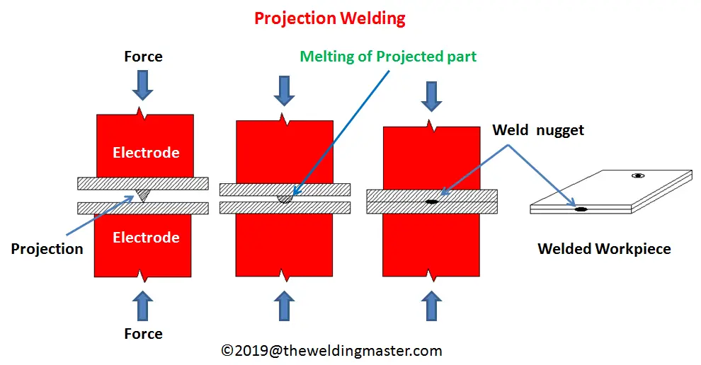
Projection welding is a resistance welding process of joining two sheets or a sheet and a thick component or a small component like nut to a big body like automotive chasis by making raised portions or projections on one of the components where weld nugget is. Shown by a dimension placed outward from flanged dimensions. Servomechanical electrode force control system is both an element and a parameter of a technology used for joining metal elements by means of resistance welding.
Short length T joints eg. Resistance and strength in the weld zone that is an inherent part of the base metal. Weld symbols used where edges joined are bent to form a flange Edge flange.
The most important variables of this assembly technique are the quality of the projections and the response of the cylinder as the projection collapses during the welding time. Resistance welding is a process used to join metallic parts with electric current. Metallographic aspect of projection welded nut 12 5 times magnification.
Projection welding is a type of resistance welding that focuses current and force to a single point or line at the beginning of a weld. Projection welding is actually a modification of spot welding the pioneer resistance welding process. EN 28167 Projections for resistance welding.
The Solenoid Valve is an electrically operated air valve in the compressed air line connected to the air cylinder on the welding machine. When the welding control applies voltage to this valve. This article focuses on the process fundamentals advantages and limitations of projection welding and reviews the equipment used in the process.
In accordance with Adobes licensing policy this file may be printed or viewed but. There are several forms of resistance welding including spot welding seam welding projection welding and butt welding. Projection welding is an ideal method of fastening attachments eg.
Although projection welding is an important and common process in industry much of the current literature focuses on process optimization and modeling 25 as opposed to evaluating electrode degradation and extending electrode life. 1 and the ef-fects of different welding para m e t e r s such as material grade welding current and electrode force were investigated in. In projection welding are consumables due to combinations of mechanical and metallurgical degradation.
14 or 15 can be made by forming projections in. Due to the fact that many dynamic and interacting parameters are involved in the resistance welding. While it can be also used to join thinner metal pieces together that tends to be a job left for spot welding.
Shown by edge flange weld symbol Corner flange welds. Projection welding has fewer variables that affect the resistance welding process as compared to spot welding. After punched a hole of 10 mm in base metals the pro-.
Brackets spigots and weld nuts to sheet metal where there is access from only one side and for making attachments to solid forged or machined parts. When projection welding high impact will damage the projection before welding and result in poor projection welds even when all other settings are correct. The projection weld-ing electrodes have been displayed in Table 1 which were made from RMAW Class Ⅱ chromium- zirconium-copper material.
PDF disclaimer This PDF file may contain embedded typefaces. Indicated by corner flange weld symbol Dimensions. The principle applied is the same seen at electric resistance spot welding ERSW but in this particular process the nut has some small protuberances which are responsible to concentrate the electric current flow to a.
Introduction To Orthographic Projection Orthographic Projection Orthographic Drawing Interesting Drawings

Joining Of Ultra High Strength Steels Using Resistance Element Welding On Conventional Resistance Spot Welding Guns Springerlink

Pdf The Other Resistance Process Cross Wire Welding

Characteristics Of Resistance Spot Welding Using Annular Recess Electrodes Sciencedirect

Welding Symbols Chart Welding Symbols Chart

Thermit Welding Welding Mechanical Engineering Mechanic

Custom Three Post Progressive Stamping Die Design Sheet Metal Fabrication Metal Stamping Dies Stamp

Image Result For Weldment Symbols Pdf Welding Symbols Auto Darkening Welding Helmet

Resistance Seam Welding Rsew Seam Welding Welding Seam


0 comments:
Post a Comment