The effective throat shall be the shortest distance from the joint root to the weld face of. In projection welding the nugget diameter depends on the selected projection diameter see Section 332.
Spot Welding Basic Parameters Setting Basic Calculations Equatio
DL 35 x t 5.

Projection welding calculations. Weld sections of typical projection welds are shown in Figure 3. Use a double-bend offset spot-welding tip with an offset nose for reaching into tight weld locations. Welding Current A R.
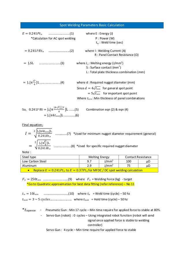
The most important variables of this assembly technique are the quality of the projections and the response of the cylinder as the projection collapses during the welding time. Weld time sec 0241𝐼2 𝑅𝑡w. The weld size is therefore 1414.
Projection welding has fewer variables that affect the resistance welding process as compared to spot welding. Part-Design Considerations for Spot and Projection Welding. For welding thin sheet an annular profile may be preferred as it has greater stability against collapse under the electrode force.
Weld Branch ASME B313 Excel Calculator Spreadsheet The calculation for Reinforcement of Welded Branch Connections has been carried out based on ASME B313 paragraph 30433. Force projection welding schedule weld schedule welding current Read more. Elongated projections based on these designs are used particularly when welding curved surfaces to ensure proper set down of the projection and adequate weld formation.
2 where I. The weld throat thickness should be 253 220 115mm. Weld Weight and Area Spreadsheet Calculator Calculations for Double V Single V Compound V Backing Strip and J groove weld weight and area.
Strength of a projection weld can be calculated to a simple approximation by area of the dimple and assuming base metal properties for sheartensile strength based on type of loading during testing. 115 162mm use 3mm fillet weld. Groove weld sizes for welds in T- Y- and K-connections in tubular members are shown in Table 36.
A 250-27 223mm. Power W tw. Projection welds developed via the resistance welding RW process use the design or shape of the part to make discreet individual-point contacts to concentrate the current during welding.
Energy J Calculation for AC spot welding P. When solid parts are to be projection welded. Spot Welding Parameters Basic Calculation 𝐸 0241𝑃𝑡w.
Posted 11215 1133 PM 5 messages. Time stays the same. 1 where E.
L Length of weld 1 unit thick From table below b d 120 150 270mm To obtain radius of Force from weld Centre of Gravity Cog. Since resistance welding represents a great value-added opportunity for metalformers its important to understand that proper part design plays a critical role. 24 Fillet Welds 241 Effective Throat 2411 Calculation.
For the calculation of adequate strength it must be considered that the specifications for the nugget diameter differ in resistance spot welding and resistance projection welding. In most applications one of the workpiece surfaces features multiple small formed projectionsround dimples elongated ridges or rings or the extended corners of weld nuts. Direction Method as BS 5950 clause 6873.
Calculations related to a welding process concerned the analysis of dynamic resistance variability momentary power of weld nugget expansion diameter and volume and energy supplied to a weld. Projection welding is a resistance welding process of joining two sheets or a sheet and a thick component or a small component like nut to a big body like automotive chasis by making raised portions or projections on one of the components where weld nugget is required to be made. Simply use the data for one spot weld and multiply current and force by three or four depending upon spot spacing.
Dnugget d1 In spot welding the nugget diameter predominantly depends on the sheet thickness. Spot welding basic parameters setting - basic calculations equations. Design calculations is permitted for weld reinforcement.
The best way is to use a known similar weld schedule to estimate for the initial test coupons.
Pdf Resistance Spot Welding A Heat Transfer Study Real And Simulated Welds Were Used To Develop A Model For Predicting Temperature Distribution Semantic Scholar
Resistance Welding Software For Simulation And Optimization Of Spot Projection Butt And Micro Welding
Projection Welding 101

Projection Welding 101

B H Curve Phenomena Of Magnetic Hysteresis With Effect And Loss Phenomena Magnetic Field Magnetic Material

Electron Beam Machining Principles Electrons Vacuum Pump Principles

Sharpening Handbook Knife Sharpening Knife Making Sharpening Tools

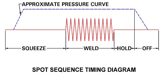
What Is The Formula For Hold And Squeeze Time In Resistance Welding How To Resistance Weld
Projection Welding 101


0 comments:
Post a Comment