As welding is considered as special processso it needs validation such as 1 Welding parameters. 2 Mechanical Engineering Department Faculty of Engineering Girne American University Girne N.
Schematic Representation Of Resistance Spot Welding 1 Download Scientific Diagram

SAR superimposes com-puter generated virtual imagery eg.
Projection welding validation. Heat input where appropriate. This article focuses on the process fundamentals advantages and limitations of projection welding and reviews the equipment used in the process. Second the percent of current control determines the percent of the available current to be used for making the weld.
Welding-validation of parameters is used to describe the assessment of a Welding Procedure Specification WPS generally in an experimental situation as opposed to a production environment. Can spot weld electrode wear lead to changes in current flow and reduced weld strength. Virtual cues directly onto the physical objects surfaces.
Projection welding can be employed and the projections are punched in the sheet opposing the face sheet. Mock-up weldment if required meets requirements with welder and welding. Can projection welding electrodes be dressed easily.
What is the life expectancy of Glidcop in resistance welding. The 70 value in a resistance welding standardspecification is typically associated with the projection welding of coinedforgedsolid weld nuts. A sleeve of plastic which is ov er-molded to one -half of the surface area of a tongue of stainless steel.
1 Determination of nugget size in resistance projection welding. Travel speed key element in heat input. Welding technique weld progression bead overlap etc.
Design Engineering Validation of. Resistance Projection Welding RPW Fundamentals The resistance welding is a pressure joint based in the melting of materials produced from the Joule effect in the contact surface electrical resistance between them generating heat during the flow of. For context the embossedstamped projection welding requirements detailed in both the RWMA Manual and the AWS C11 only state what sort of weld strength is required not the required weld size.
A large flat electrode on the face side can minimise marking as with spot welding provided that the mechanical wear of the electrode in the form of a shallow indentation is controlled. Congruent laminate - a shielding tape which has a layer of foil a layer of a fabric-carrier and a layer of adhesive. The weld current is the current in the welding circuit during the making of a weld.
Preheat and interpass temperatures. The materials are Kovar 29Ni17-CoBal Fe alloy CTE of 6 PPM with 127µ AuNi plate on top. An Article titled Validating the Resistance Welding Process.
What is the ideal dressing frequency for coated material. WELDING Our welding department utilizes several technologies to fuse metal stampings nuts studs and pipe in the manufacturing of automotive suspension and body assemblies. The Quality Test Lab of DYNA-MIG A Division of FP Mfg Inc.
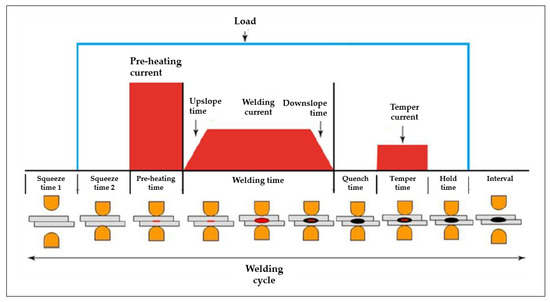
First the setting of the transformer tap switch determines the maximum amount of weld current available. The virtual cues act as visual aids to help the operators weld in the correct location. Welding or projection welding.
2 The operators must be trained and skilled to do the job. A number of welds can be made simultaneously. Alongside existing plant infrastructure.
Laser projection allows companies to speed up welding processes minimize the use of templates and tools eliminate errors and improve quality The TracerSI is not impaired by dusty work environments and the projector is sealed against environmental contamination. Projection welding of TO style packages is a resistance welding process used to join cover and package. Why suddenly can I not attain the desired current in one cycle without upslope.
Is able to provide process validation from development stages right through to mass production. Projection welding is a variation of resistance welding in which current flow is concentrated at the point of contact with a local geometric extension of one or both of the parts being welded. Was published in the December 2009 Issue of the Welding Journal at.
Product process tooling and fixturing assembly machinery. The projection sys-tem becomes an active part of the welding process ie. Prototype Design.
Welding services are customizable by project requirements using automation when possible to reduce cost while ensuring strength and durability. Numerical method with experimental measurements Danial Mohammad Rezaei1 Behzad Heidarshenas2 Fazel Baniasadi3 1Department of Mechanical Engineering University of Tehran Tehran Iran. Welding function can be standalone or incorporated into the fabrication of your product using dedicated assembly cells.
The amount of weld current is controlled by two things. Equipment settings such as amps volts and wire feed. Must be as per defined standards.
Robust weld strength validation per application requirements. 3 The destructive testing must be carried out as per defined frequencycustomer rqmnt. 3 layers of plated-metal such as Chromium top Nickel middle and Copper.
The weld is an alloy of Kovar AuNi which is corrosive-resistance and compliant with MIL-STD-883 Test Method 1009 Salt Atmosphere. Temperature pressure colling water temp etc. Hard-Gaging.
Standards And Testing Spottrack

Estimation Of Lobe Curve With Material Strength In Resistance Projection Welding Sciencedirect

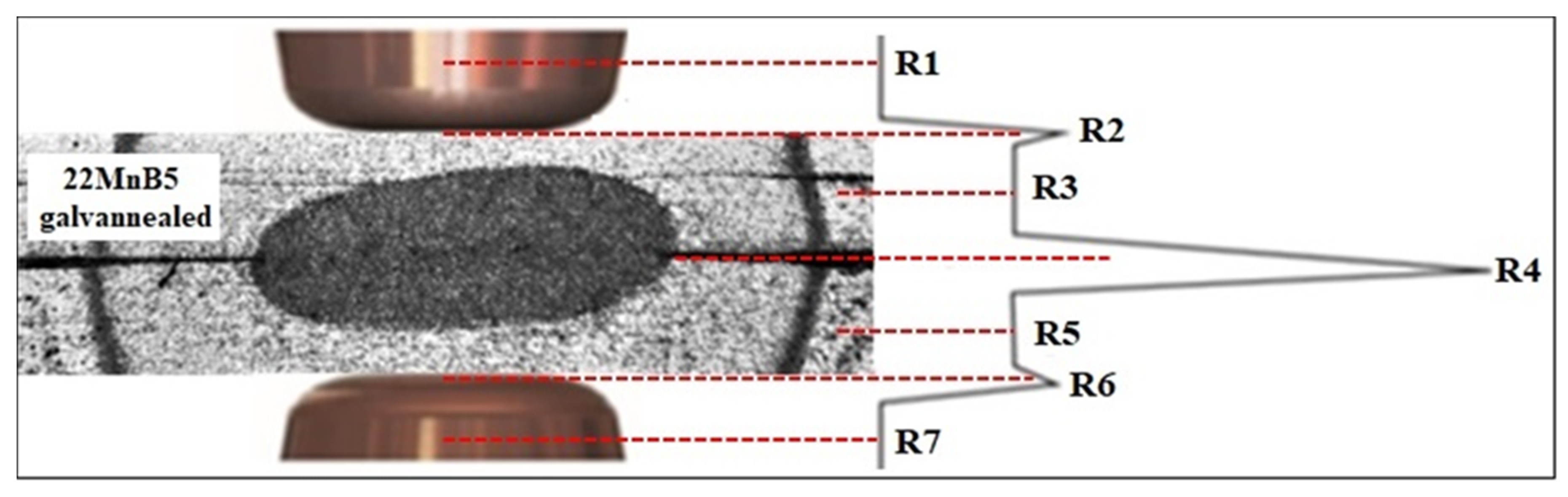
Metals Free Full Text Optimization Of The Resistance Spot Welding Process Of 22mnb5 Galvannealed Steel Using Response Surface Methodology And Global Criterion Method Based On Principal Components Analysis Html
Spot Welding Technical Information Tite Spot Welders
Metals Free Full Text Optimization Of The Resistance Spot Welding Process Of 22mnb5 Galvannealed Steel Using Response Surface Methodology And Global Criterion Method Based On Principal Components Analysis Html
Spot Welding An Overview Sciencedirect Topics

Characteristics Of Shunting Effect In Resistance Spot Welding In Mild Steel Based On Electrode Displacement Sciencedirect

Spot Welding An Overview Sciencedirect Topics

Schematic Of Shunting In Resistance Spot Welding Download Scientific Diagram


0 comments:
Post a Comment