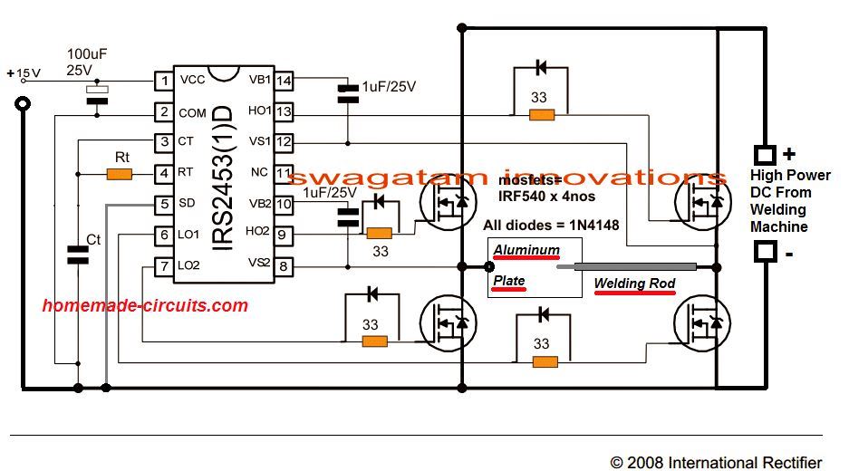
But I used Irgpc40u igbtsingle each side and sg3525 pwm. A full bridge topology is used to implement the DC to AC inverter.
Smps Welding Inverter Circuit Homemade Circuit Projects
Converter is a popular topology often used in industrial welding machines with low-to-medium power requirements.

Welding inverter topology. Using Two Switch Topology When developing a welding inverter I applied forward inverter with two switches topology. Small reverse recovery loss Duty control method IGBT. The most common topologies in welding inverters are full-bridge half-bridge and two-switch forward.
Switched-mode power supplies SMPS and welders. However as the switch-on current pulse tends to be high there needs the presence of softstart circuit. New topologies of single-phase inverter welding supplies with increased power factor are proposed.
Finally most square wave inverters have mediocre efficiency typically about 80 and the idle power draw is relatively high. The switching frequency of the high side and low side IGBTs are 20 kHz and 60 Hz. In my article about switchning supplies it is a topology IID.
The most common control scheme used in welding applications is the constant current. Accuracy in P I control - better welding process. In a main full-bridge inverter-based topology welding operation the incoming AC 5060 Hz main power single or three-phase is first rectified to DC and then is fed into the inverter section of the power supply where it is alternatively switched on and off by the transistor switches at high frequencies.
Small reverse recovery loss IGBT. If you are looking for an option to replace conventional welding transformer the welding inverter is the best choice. The need to increase the power factor of welding equipment is dictated by the introduction of.
Characteristics on the welding output load. As shown in Figure 14 the bridge is used to generate a high-frequency square wave that is fed to an isolation transformer. Zero voltage zero current switching at turn on and hard switchingat turn off.
You have to take into account 100W transistor loss for decent welding work induction cooker transistors are not designed for high dissipation of heat high silicon to case thermal resistance unless you design fancy resonant welding inverter high speed IGBT have higher Vce sat low Vce sat IGBT high switching loss in joules if it all is black magic best option is to look for designed for Welding. The duty ratio varies. In comparison half bridge inverter topologies are more power efficient and cost effective.
Figure 11 Figure 12 Figure 13 Figure 14 Figure 15 and Figure 16 show the above mentioned topologies and their usual operating waveforms 910. During positive output half cycle Q1 is sine pulse width modulated sine PWM while Q4 is kept on. Higher Power-density compactness weight With PFC more power out of a single-phase Application Overview - Welding.
The majority of welding machine include inverters. A full bridge inverter also called an H-bridge inverter is the most efficient inverter topology which work two wire transformers for delivering the required push-pull oscillating current into the primary. During negative output half cycle Q2 is sine pulse width modulated while Q3 is kept on.
Topology in Welding machine IGBT. In order to provide the voltage that corresponds to full load conditions 25V40A the standard topology should operate with a dutycycle smaller than 50 whilst in the proposed topology the H-bridge inverter can. On the output side of the welding equipment a transformer ratio of 106 is needed.
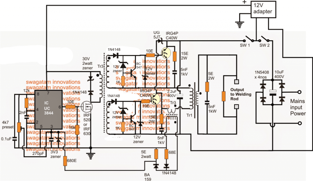
The output stage at the transformer. The current control is maintained through potentiometer. Since the inrush current of those capacitors would be too high theres a softstart circuit.
Welding inverter is handy and runs on DC current. This avoids the use of a 3-wire center tapped transformer which are not very efficient due to their twice the amount of primary winding than. I have build a welding inverter using two switch forward reference based httpdanykcz.
Input mains voltage passes through an EMI filter and is smoothed with high capacity capacitors. The inverter stage in this hard-switched forward topology includes two transistor switches and two fast recovery diodes placed at each end of the high-frequency power transformer primary winding. Figure 2 Push-Pull Topology - Square Wave Output AC Output Square Wave Transistor Transformer Switch Transistor Switch Battery Negative Battery Positive Battery Negative Current Flow AC Output Square Wave.
Using Two Switch Topology. Here the input line voltage traverses through the EMI filter further smoothing with big capacity. For this inverter i chose topology which is the most common in welding inverters - forward converter with two switches.
This topology is most commonly used in three classes of applications. Small turn on and large turn off loss. When developing a welding inverter I applied forward inverter with two switches topology.
Zero voltage switching at turn on and hard switching at turn off. This is because the output current of the welding machine can be as high as several hundred ampere and there are two semiconductor switches in the second stage full bridge inverter conducting current at.

Hobby Electronics Circuits Smps Welding Inverter Circuit Electronics Circuit Inverter Welding Machine Electrical Engineering Books

Igbt Inverter Welder Schematic Manual Igbt Inverter Welding Machine Circuit Diagram
Figure 1 From Research On Digital Soft Switch Welding Cutting Inverter Power Source Semantic Scholar

Figure 1 From A 10 Kw Single Stage Converter For Welding With Inherent Power Factor Correction Semantic Scholar
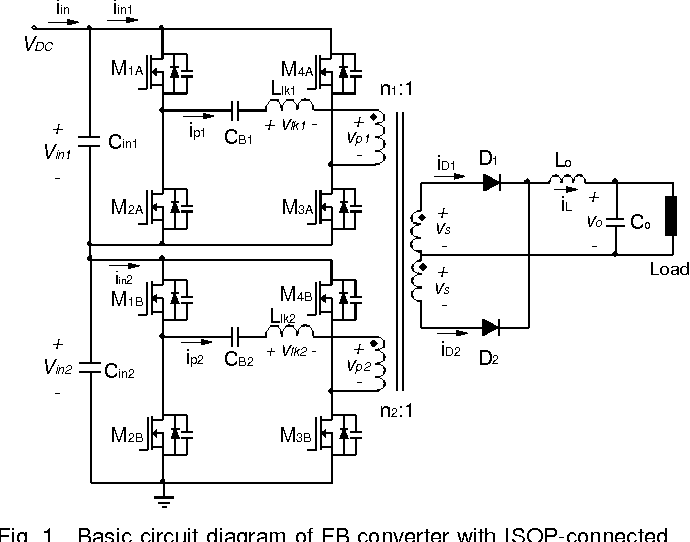
High Efficiency Portable Welding Machine Based On Full Bridge Converter With Isop Connected Single Transformer And Active Snubber Semantic Scholar
Smps Welding Inverter Circuit Homemade Circuit Projects

Wiring Diagram For Peavey Patriot Inverter Welding Machine Inverter Welder Circuit Diagram

Switch Mode Arc Inverter Welder Schematic Page 4 Forum For Electronics

Welding Inverter Up To 100a Inverter Welding Machine Welding Machine Inverter Welder


0 comments:
Post a Comment