After a few milliseconds of interfacial heating the force wave may be applied. Low-Force Friction Welding falls in the middle of the continuum.
Https Core Ac Uk Download Pdf 216949319 Pdf
1 Weld Trimming 2 Weld alignment 3 Weld appearance.
Welding upset force. Because of the element of preheat with Low-Force Friction Welding you can make very low upset welds they take on more of a bulge shape as opposed to the predominant flash curl typically generated by traditional friction welding. Upset force and one-side chamfer angle. The coalescence is produced over the entire area by the heat generated from the resistance of the electric current flow through the contact area of the abutting surfaces.
A high conductivity electrode against the lower. Additional heat may be applied as needed during the upset portion of the weld to both assist in forging and to control cooling. During the upset segment of the weld a rapid application of force drives the molten surfaces into one another.
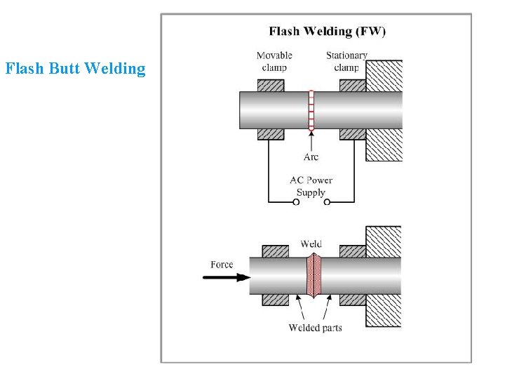
Copper and aluminium for example form a series of brittle phases when melted together but flash butt welding of copper to aluminium is widely practised since these phases are forced out of the joint when the upset force is applied. The upset force and length of upset are important in achieving correct forging of the weld. Upset welding UWresistance butt welding is a welding technique that produces coalescence simultaneously over the entire area of abutting surfaces or progressively along a joint by the heat obtained from resistance to electric current through the area where those surfaces are in contact.
Many textbooks said that the upset welding is the typical resistance welding process. Upset force variations of 105 14. Welding Parameters Welding current Upset force Pressure Displacement Welding time Programmed identification and setting details.
This forging action results in residual molten material being expelled and forging of the underlying solid metal. Pressure Butt Welding br-er7-03ecdr before upset force has been applied water-cooled clamping chucks Cu electrodes upset force _ bulging at the end of the weld Figure 73 Schematic Structure of a Flash Butt Welding Equipment br-er7-04ecdr secondary side fixed clamping chuck mobile clamping chuck clamping force steel chuck copper shoe ab b. The applied force is maintained throughout the heating period.
Force Electrode Size Design Material Heat Balancing Holders Weld Gun Adapters Shanks Single and Double Bend Shanks Barrel Holders Equalizing Holders High Pressure Welding Adapters Multi Welding Weld Schedules Projection Welding Electrodes AlloysMaterials Cooling. In case of the higher upset force of 10 kN the upset force more dominant to affect torsion strength of the continuous drive friction weld CDFW joint. In many cases this process can achieve welds with little to no loss of length upset.
Smooth Flash Low Upset. The flash is formed as a smooth bulge instead of a pair of curls as with traditional friction welding. The force wave can be electronically timed in relation to the welding current.
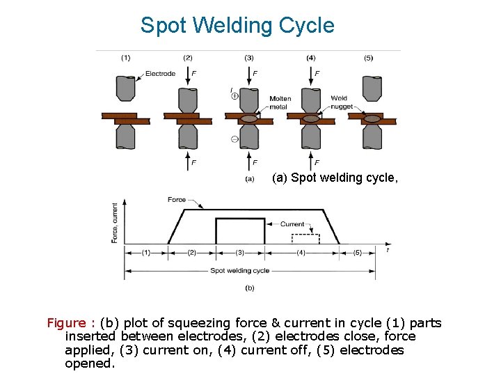
Commercial round bar aluminum alloy A6061 and carbon steel S15C were used as rotated and a stationary part respectively in continuous drive friction welding CDFW process. Simple sturdy and reliable equipment operated by unskilled workers. The process can be and shall be explained with the simple one- dimensional heat conduction model Electro es Squeeze Heating time Electrode force ding current Start Of process Movement Of n Time Upset Forge force Upset distance Distance to start upset tm e Current.
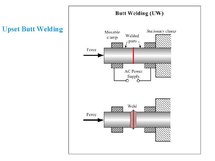
Like other Resistance Welding Processes Upset Welding uses heat generated by resistance to the flow of welding current as well as force to push the workpieces together applied over a defined period of time. Upset welding UWresistance butt welding is a welding technique that produces coalescence simultaneously over the entire area of abutting surfaces or progressively along a joint by the heat obtained from resistance to electric current through the area where those surfaces are in contact. Rapid upset created by this force expels oxides and impurities from the weld.
This eliminates melted metal and contaminants from the joint producing a sound solid phase weld forge weld. Ease of parameters control only current time and force High quality absence of typical fusion defects. Commercial round bar aluminum alloy A6061 and carbon steel S15C were used as rotated and a stationary part respectively in continuous drive friction welding CDFW process.
A Friction Weld at a Fraction of the Force. Metallurgical properties comparable to those of hot worked material. The specimen with maximum torsion strength has more precipitates in grains of microstructures compared to that of specimen with lower torsion strength.
An effort to increase the tensile strength of dissimilar friction weld joint of round bar A6061S15C was done in this study using upset force and one-side chamfer angle. In-machine post-weld resistance heating of highly hardenable materials may be beneficial in reducing the risk of cracking. MFUW controls can be set for short weld current times.
Magnetic force upset welding MFUW differs from conventional resistance welding in that a forging weld force is applied by a 120-hertz electromagnet. When spot welding dissimilar metals it may be necessary to use electrodes of differing conductivity against the different parts ie. In the upset welding process no flash occurs.
4 Non-Destructive testing 5 Bend testing.

Fatigue Life Prediction Of Different Joint Designs For Friction Welding Of 1050 Mild Steel And 1050 Aluminum

Pdf Design And Development Of Micro Upset Welding Setup Semantic Scholar
Resistance Welding Is A Pressure Welding Technique Using

Vi Magnetic Force Upset Welding Parameters And Download Table
Resistance Welding Is A Pressure Welding Technique Using
Resistance Welding Is A Pressure Welding Technique Using

Diagram Of Welding Speed And Forces During The Direct Drive Friction Download Scientific Diagram

Diagram Of Welding Speed And Forces During The Direct Drive Friction Download Scientific Diagram

Pdf Design And Development Of Micro Upset Welding Setup Semantic Scholar


0 comments:
Post a Comment