Designandoperation ofan ultrasonicweldingunit 4 3. Also since the Z-loss factor is dependent on the welding process and position of welding variables the engineer will not likely know the solution can be custom-ized around the contractors preferences.

The Mechanical Characteristics Of Each Type Of Welded Joints For Smaw Download Table
2252 paragraph 2 For welds between parts with surfaces meeting at an angle less than 80 or greater than 100 the shop drawings shall show the detailed arrangement of welds and required leg size to account for effects of joint geometry and where appropriate the Z-loss reduction for the process to be used and the angle A24 613.
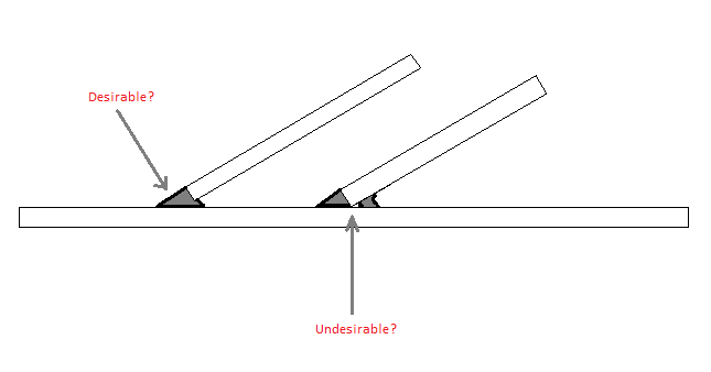
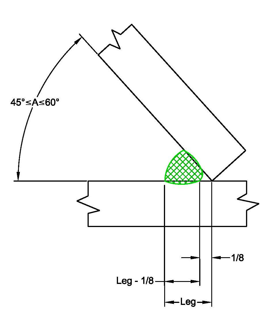
Welding z loss factor. Annex B of AWS D11 lists the factors to be used when sizing fillet welds in Skewed T-joints when the dihedral angle is 95 degrees down to 60 degrees. The amount of poor quality weld in the root of the joint is a result of the combination of the dihedral angle the welding process and the position of welding. The Z-Loss dimension accounts for the probability of incomplete fusion at the root of the joint on the acute side of the connection due to restricted welding access.
ReH_weld 400 for welding of high strength steel with ReH 390. ReH_weld 375 for welding of high strength steels with ReH from 265 to 355. Thicker joints can tolerate additional poor welding at the root loss factor Z.
The Z loss factor is applied at angles below 60 degrees to recognize that this weld cannot reliably penetrate to the root of the joint and is thus a partial-joint-penetration groove weld. Last modified 13 September 2002. When this is done the fabricator shows on the shop drawings the placement of welds and the required leg dimensions to satisfy the.
In the ideal case the losses are zero and the dielectric loss factor is zero. Ad Find China Manufacturers Of Welding Electrode. UltrasonicweldingofHoechst engineeringplastics 5 31 Requirementsfor optimum ultrasonic welds 5 32 Factors affecting weldingproperties 6 321 Effect ofthe mouldingcompound 7 3211 Effect ofmeltviscosity 7 3212 Effect ofpigments 7 3213 Effect ofreinforcing materials.
Tas-built as-built thickness of the abutting plate in mm. Note that below 30 degrees this joint is no longer prequalified. Welding of GMAW fillets on medium carbon steel plates S50C with variations in welding currents 90 A 100A and 110A and carried out at.
τeH_weld specified shear yield stress of weld deposit in Nmm 2. For the 30 weld at detail D the loss factor is 10 mm. In the case of the capacitor mentioned above the dielectric loss factor is given by the ratio of the charging current 90 out of phase to the applied voltage to the loss current in.
That is all the. Degrees the D11 Code requries the application of a Z-loss factorThus the values in Table 1 that apply to dihedral angles where this applies are shown in blue numbers to remind the user to incorporate this factor into the weld throat sizes. Z-loss is not addressed by all fabrication codes and is not considered by some designers but it certainly should be considered regardless of what fabrication standard or code is used for design.
The PJP parameter definition needed to be prioritized. Loss Factor η Point of Measurement Cold-rolled Steel Sheet Relation Between Loss Factor and Oil Temperature When VIBLESS is Used in Oil Pans Fig. 937 778-8947 Canada.
The heat loss due t o coupled convection and radiation is. Here 3 mm for welding groove angles down to 45. Set the air into motion Pv part aka acceleration loss Overcome any losses in the hood Note ideally when no losses Psh PV.
Influence of Dihedral Angle AWS D11 Structural Welding CodeSteelprovides for five. 937 615-3598 11 90 Table 3 - Friction Losses Through Pipe Fittings in Terms of Equivalent Lengths of Standard Pipe. Specifically the Z loss factor is to be accounted for.
ReH_weld 355 for welding of normal strength steel with ReH 235. PT1 PT2 losses D 5 D P sh P sh hood static pressure Note. 21 shows that the loss factor decreases with the increase in the initial amplitude of vibration at the free end of the beam model although the increase in the amplitude of vibration raises energy.
Outside P T1 1 atm and P V1 0 so P T1 gauge 0 Point 1 Point 2 Hood entry losses Psh T Peh sh is the pressure needed to. Ad Find China Manufacturers Of Welding Electrode. 4 VIBLESS 126 200 315 500 800 125K 2K 315K 5K 8K 10 20 30 40 50 Ordinary Sound 90 dB Intense Sound 110 dB Vibration-damping Sheet Steel Sheet Mass Line Frequency Hz Sound Transmission Loss.
905 457-6223 International. The dielectric loss factor is a measure of the energy absorbed in the medium as an electromagnetic wave passes through that medium. The Z-loss factor is used to account for the likely incidence of poor quality welding in the root of a joint with a small The practical application of this principle is that when welds included angle.
Variation of loss factor with length for jointed and welded cantilever beams of dimensions 402 3 mm 2 and amplitude 02 mm. The z loss factor is used to account for the likely incidence of poor quality welding in the root of a skewed joint.
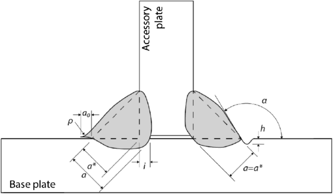
Development Of A Computational Fatigue Model For Evaluation Of Weld Quality Springerlink
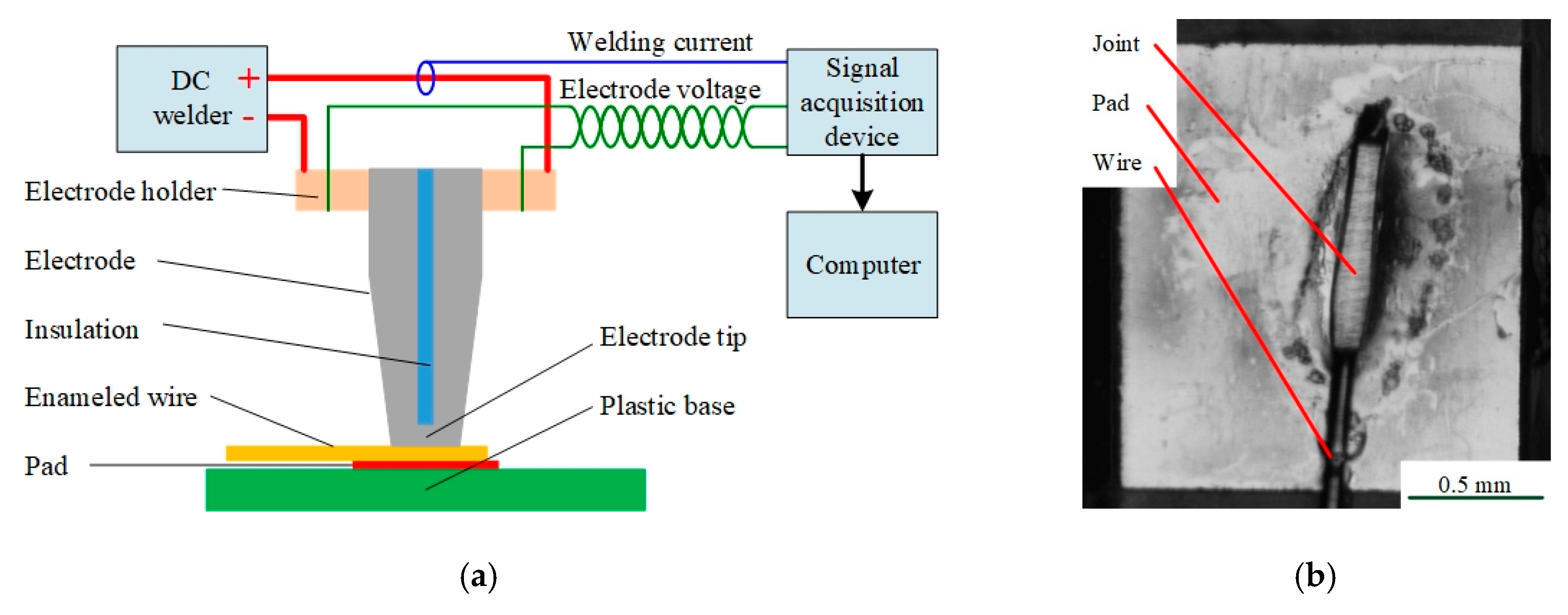
Applied Sciences Free Full Text Quality Monitoring For Micro Resistance Spot Welding With Class Imbalanced Data Based On Anomaly Detection Html
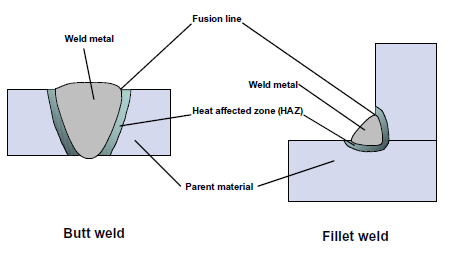
Welding Steelconstruction Info
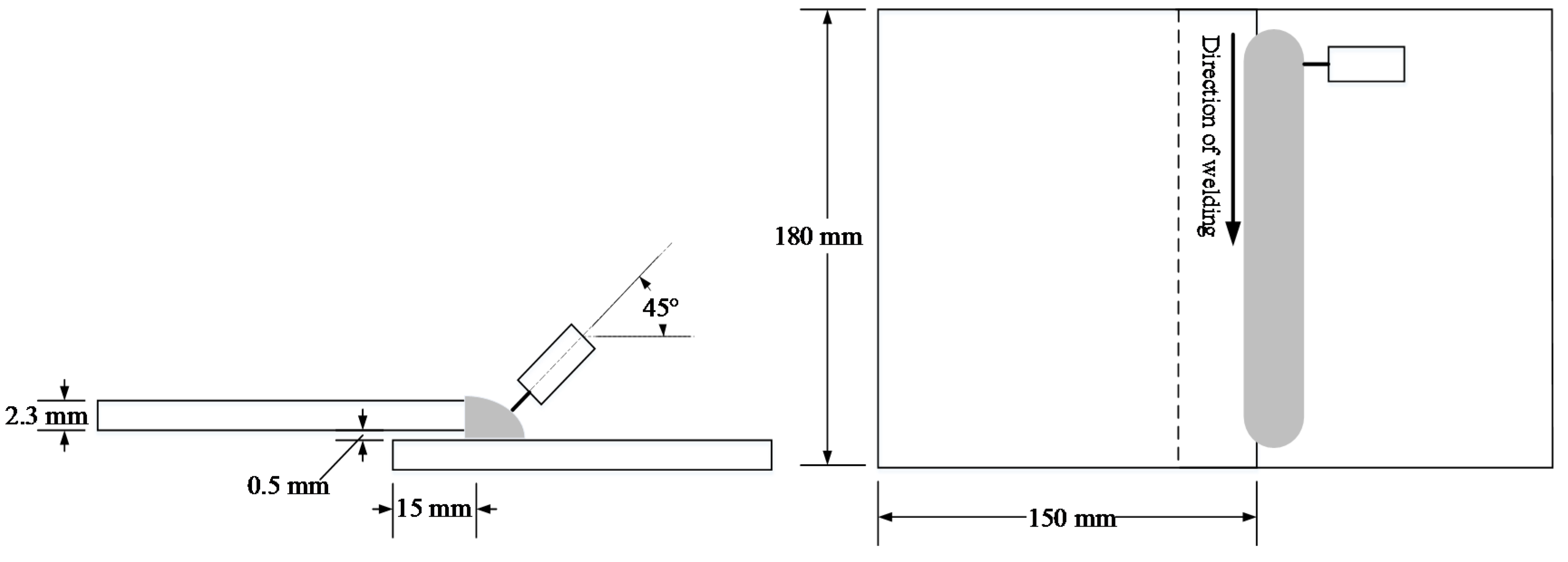
Metals Free Full Text Real Time Detection Of Weld Defects For Automated Welding Process Base On Deep Neural Network Html

Designing Fillet Welds For Skewed T Jointsa Part 1 The James F

Effects Of Dilution On Alloy Content And Microstructure In Multi Pass Steel Welds Sciencedirect

0 comments:
Post a Comment