Brackets spigots and weld nuts to sheet metal where there is access from only one side and for making attachments to solid forged or machined parts. Be alert that welding sparks can easily go through small cracks and.
Resistance Welding Spot Welding Welding Album
The most important variables of this assembly technique are the quality of the projections and the response of the cylinder as the projection collapses during the welding time.

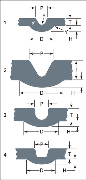
Projection welding design guidelines. Some projection welding does not require a design as in cross wire welding. Projection height is typically 1 to 2mm depending on sheet thickness and weld strength required. Part-Design Considerations for Spot and Projection Welding June 1 2018 Use a double-bend offset spot-welding tip with an offset nose for reaching into tight weld locations.
Welds including end returns or boxing shall be indicated on the design and detail drawings. Over time individual manufacturers performing projection welding developed standards based on nugget size as an alternative to pulling tensile tests. Throat Size 18 75o 38 h plate thickness weld size Butt h 0707 plate thickness 0707 weld size 14 Fillet.
For context the embossedstamped projection welding requirements detailed in both the RWMA Manual and the AWS C11 only state what sort of weld strength is required not the required weld size. Projection welding has fewer variables that affect the resistance welding process as compared to spot welding. Usually two or three projections are welded at the same time.
Projection welding is an ideal method of fastening attachments eg. 14 or 15 can be made by forming projections in the edge of the stem. General rules for machined annular projections.
Merely place the two wires in contact at 90. Projection welding is an electrical re-sistance welding process in wh i c h resis-tance welds are produced at localized points in workpieces held under pressure between suitable electrodes. 13 Guidelines for Projection Welding Operations 14 Guidelines for MIG Welding Operations 15 Guidelines for Self-Piercing Rivets SPRs 16 Welding Considerations for Different Materials 17 Design for Laser Welding in Assembly 18 Other Product Design Considerations 19 Guidelines for Flanging and Hemming 110 Summary Classroom Exercises.
A recess adjacent to the projection is sometimes used as a spit trap. Remove all flammables within 35 ft 107 m of the weld. Avoid positioning the projection on the components edge.
Static Strength of Welds FFNormal Shear F w h F w h 2F F F 18 75o 38 14 Max Normal Max Shear F 0618w h F 0707w h Butt Fillet h throat size. If this is not possible tightly cover them with approved covers. In lap joints between parts subject.
The projections are usually made by forging embossing or by intersection and may be button or dome type ring type shoulder projection cross wire welding and radius projection. Coined or machined projections do not cause the same concerns as a stamped projection as there is no risk of premature projection collapse during welding. When long seam is to be projection welded then the limit is usually 250 mm length.
Fillet weld termina-tions may extend to the ends or sides of parts or may be stopped short or may be boxed except as limited by 2472 through 2475. Short length T joints eg. Projection welds developed via the resistance welding RW process use the design or shape of the part to make discreet individual-point contacts to concentrate the current during welding.
Projection included angle should normally be 90. With more than three simultaneous welds however there is a tendency for lack of consistency and the welds may not have same shape or strength. Mostly in almost all applications with various small projections are molded on single parts surfaces which need to weld.
Protect yourself and others from flying sparks and hot metal. The shape and size of coined or machined projections are unlimited but a dome shape with a diameter-to-height ratio of 3-to-1 is a good starting point. Usually two or three projections are welded at a time though in specially designed heavy machines 4 to 5 projections have been successfully welded at one time.
Do not spot weld where flying sparks can strike flammable material. In most applications one of the workpiece surfaces features multiple small formed projectionsround dimples elongated ridges or rings or the extended corners of weld nuts. Projection welding is one kind of resistance weld where the shape or design of the part is used to make subtle point contacts to concentrate the current during welding.
Although tests indicate satis-. The projec-tions are usually dome or cone shaped and are made with different designs ac-cording to recommendations of some standards. The sizes and designs will depend upon the material being welded its thickness and the design and location for the projection.
Since resistance welding represents a great value-added opportunity for metalformers its important to understand that proper part design plays a critical role. Projection welding is performed with many style projections - rings dimples and slots to name a few.
Pin By Susan Urbaniak On Michael S Mechanical Engineering Design Geometric Tolerancing Mechanical Design
Part Design Considerations For Spot And Projection Welding Metalforming Magazine Article
What Electrode Face Design Is Best For My Application How To Resistance Weld
How Do You Design A Projection For Resistance Welding How To Resistance Weld
Diagram Showing Basic And Supplementary Weld Symbols And The Standard Location Of Elements Of A Welding Sy Blueprints Electrical Plan Symbols Blueprint Symbols
Chapter 5 Welding Joint Design And Welding Symbols
Chapter 5 Welding Joint Design And Welding Symbols

0 comments:
Post a Comment