These forces are a result of the ultrasonic vibrations of the tool pressed onto the parts to be welded. During the ultrasonic welding process mechanical vibrations with defined amplitude force and duration are applied to the materials to be welded.
Lateral Torsional Buckling Strength Calculations Download Scientific Diagram
For this article the amplitude and welding modes are considered.

Ultrasonic welding force calculation. Medium welding tool of ultrasonic oscillatory system and welded materials 5. The vibrations generate heat at the joint interface of the parts being welded resulting in melting the thermoplastic materials and weld formation after cooling. Sensitive to the combination of clamping force and ultrasonic vibration amplitude of the welding tip but there are optimal combinations of these and also limits that must be clearly identified.
To achieve a constant quality the welding time is automatically adjusted. These waveforms are the simplest of all other waveforms. The main goal in this study is.
The core of the ultrasonic welding. There are a number of parameters that must be selected correctly in order to achieve good ultrasonic welds. With ultrasonic welding high-strength liquid-andgas-tight joints canbeproduced.
Intensity of ultrasonic oscillations 1 is formed on a radiating surface of ultrasonic oscillatory system which can be presented as 0 0 2 0 2 I0 2p f A r c 1 Considering that at ultrasonic welding full acoustical contact welding tool of ultrasonic oscillatory system and. By power curve is giving information for the splice quality. With a constant energy setting is known from ultrasonic plastics welding and can also be used for ultrasonic metal welding.
1000W 1500W etcCan you please tell how to calculate this power and what parameters are required for this. Ultrasonic weldingis an ideal process for jointing ciga rette lighter tanks valve bodies andsmall containers assemblingparts for electrical equipmentandfor use in the automotiveandhouseholdapplianceindustries. Interstitial oxides Introduction Ultrasonic welding can be defined as a solid-state joining process.
Since the ultrasonic vibration is a sinusoidal motion VPifD where Pi is. The power required for ultrasonic welding. Power curve shows how the ultrasonic welding process went.
Longitudinal waves Figure 6 are also called as straight or compressional waves. The results obtained are as follows1 The clean condition of the specimen surfaces contacting with welding tip anvil is desirable for successful welding2 Adequate material such as certain. Vibration amplitude frequency.
Although this type of quality control is good with ultrasonic plastics welding the approach has to be. During ultrasonic welding of sheet metal normal and shear forces act on the parts to be welded and the weld interface. Illustration of Pull out test performing of splice with wires combination - left side.
Ultrasonic welding 131132133 the most widely used welding method for thermoplastics uses ultrasonic energy at high frequencies 2040 kHz to produce low amplitude 125 μm mechanical vibrations. The exact force will be determined based on. Three basic modes of propagation of sound energy in metals are being used in Ultrasonic test these modes are.
Welding in energy mode ie. Ultrasonic welding actuators are typically pneumatic or electric driven and provide a weld force in the range of 50-750 lbs. For a 20-kHz ultrasonic-welding process for example polystyrene PS requires 15 to 20 m 0 to peak and high-density polyethylene HDPE needs 45 to 50 m 0 to peak.
These include vibration amplitude welding mode downspeed trigger pressure weld time hold time. Normal load or weld clamping force lb Electric power input to the transducer watts Optimum electric power input watts Normal stress at the contact area psi Maximum normal stress at the contact area psi PmM 3N2 IT a2 S Tangential shear force lb t Ultrasonic pulse time or weld time sec. PFV where F is clamping force V is sonotrode vibration velocity.
Generally for a rotating spindle in any machine we calculate spindle power as 2piNT60 Watt where Nspindle speed in RPM and T is torque in N-Meter. 1 time 25 mm² right side 2 times by 35 mm². X tg 1 c Zx Sx c tg t 8 Where Sx is the cross-sectional area of the horn at distance x.
Force after removing a series of forces is not greater than 005 full rated output. Fx Zx vx 7 After doing the calculus. Furthermore they determine the weld quality and the power that is needed to produce the weld.
In a point of a structure the mechanical impedance is given by the ratio between the acting force and speed. Due to intermolecular and surface friction heat is generated and melts the material. All ultrasonic generator manufacturers are telling the power in terms of watts.
Thetechnologyhas beendevelopedto the stage where. Actuators used in metal ultrasonic welder may by driven by hydraulics and see more force.
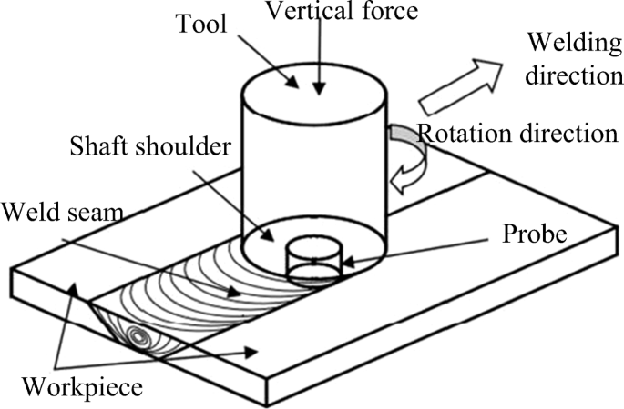
A Measurement Method Of Weld Temperature And Tool Positioning During Friction Stir Welding Process Springerlink
Calculation Results A Heat Flux B Current Density And C Plasma Download Scientific Diagram
Tension Flange Yielding Strength Calculations Followed By Selection Of Download Scientific Diagram
A A Schematic Diagram Of The Ultrasonic Welding System B Partial Download Scientific Diagram
Ultrasonic Plastic Welding Will Be More Widely Used In The Future
The Measured Welding Forces During The Ultrasonic Welding Process Download Scientific Diagram
Bending Force Calculation Metal Bending Metal Bending Tools Sheet Metal
Flange Local Buckling Strength Calculations Download Scientific Diagram

0 comments:
Post a Comment